Fluidized Sand Bed

Fluidized Sand Bed

Choosing the Right Dinamec Systems Fluidized Bed for Your Application

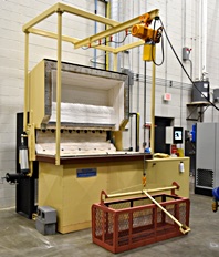
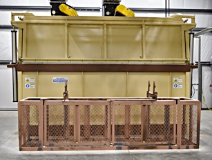
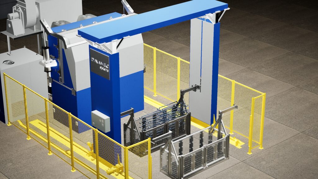
A range of standard Dinamec Systems Fluid Clean machine configurations is available to comply with your particular cleaning needs. Our experienced engineering department, combined with a flexible production department allows us to offer custom-made installations for special projects.

D-Type ICV

F-Type ICV

E-Type ICV

Fluidized Bed Dimensions
Inside of Bed
Standard Machines
All Models Are Available in RAN (flat hood) and ICV (clam shell hood)
Loading Basket
(inner dimensions)
Maximum Loading
(Steel)*
Organic Load**
Model LxW/DxH (inch) (lbs) (lbs/batch)
E-151010 51 x 33 x 38 1278 15-43
E-201010 70 x 33 x 38 1837 19-54
E-251010 90 x 33 x 38 2296 25-71
E-301010 110 x 33 x 38 2755 29-82
G-080606 23 x 17 x 22 128 4-11
G-160606 54 x 17 x 22 272 7-21
G-220808 78 x 25 x 30 735 14-26
FS-240808 86 x 25 x 30 751 17-48
FS-301011 110 x 33 x 41 2071 30-86
FS-201611 70 x 56 x 41 2258 33-91
FS-301213 110 x 41 x 49 2671 39-111
FB-401011 153 x 33 x 41 2771 41-115
FB-341414 125 x 49 x 52 4530 54-152
FB-321616 117 x 56 x 61 5748 62-174
FB-441814 165 x 64 x 52 7885 89-252
*Amount of steel not including the basket that can be loaded into the machine (do not deduct the basket)
**Depending on capacity of thermal afterburner and type of organic/plastic contamination
Custom sizes available upon request

All dimensions are in inches. Please note that the capacity of our machines are not exclusively determined by the bed volume. Also to be considered are the type and amount of organics removed and the amount of metal to be processed.

PLC based control system with 15″ color touch screen Operator Interface

Features Include:

  • Main operator screen – Used to set cycle time, enter temperature set points, Graphically show machine operation, show text based messaging for machine operation and alarm conditions, access other system screens.
  • Alarm condition history with date and time stamp.
  • PLC input and output status screens – Used to indicate the PLC I/O description, status and on/off state or value.
  • Manual override screen – Used to force the various valves on and off for trouble shooting purposes.
  • Graphs of bed and exhaust temperatures.
  • System configuration screens.
  • Password protected loaded shutdown reset screen.
  • Resettable and non resettable run time meters.
  • Complete set of Electrical drawings.
  • Additional screens include:
    • Main Menu
    • System Information
    • Modify Set Point
    • Manual Override Help